
- How did our switch behave in case of cable damage and short circuit on an active PoE port? if some wires will then have a short circuit (during operation)? What will happen in the switch? Is there some kind of protection without any damage (e.g. burned fuse)?
1. Our PoE switch (PSE chip) had 2 kinds over load protection
Surge current protection: over current af: 892mA at:1200mA)
PSE chip also can offer over 15.5W/30W in af/at mode(max af: 448mA, at: 767mA), when over max current also cute off power.
2. UL must test POE system in shorted that system must enable protected function. Chip vender had approved by UL.
3. Volktek design fuse for double protecting in over load or shorted to protection PSE chips in all PoE switch.
4. If over current over fuse spec, fuse will be destroyed.
- Giving Proper Maintenance1. Prevent against network stormsCorrect configuration of the network, using a robust ring resiliency protocol between the switches is necessary for network redundancy as well as loop prevention. One can prefer ERPS or Xpress rings for industrial use as their network recovery rate is below 50msec.2. Proper configuration for high-Security authentication on all connected portsSwitch ports should be set up to never allow data exchange with a connected device until that device has provided authentication credentials that have been verified by the network’s authentication server. The switch ports which are not used should be disabled/shut down to prevent being hijacked in any way.3. Real-time network AlarmVolktek provides various options for real-time network alarm from hardware to software. With 24V/1A terminal connection through hardware to allow connects to the alarm system. Standard network management protocols, Syslog, Email Alarm provide messages that are sent upon state change like ports being plugged or unplugged, un-authentication access etc. Network Management Stations receive and display these alarms so that necessary action can be taken on the network connected devices.
- Best Practices for Installation
These general installation and maintenance instructions are provided by the Volktek support team. Always follow standard recommendations relating to proper installation, testing, maintenance, and reconditioning. In order to maximize system capabilities and avoid potential pitfalls, installers need to have an understanding of the best practices in configuring Ethernet network infrastructure for the factory floors.
Installation
Protect the Industrial Ethernet Switches from Environmental and Human Harm
Place the switches in proper location and follow up all necessary actions before installing the Industrial switches.I. Do Proper Earthing:
The Switches, Network Cabinet, and Rack to be placed in buildings or installation sites are kept above certainheight from the ground level.1. Why we need to do proper Earthing?
✓ To prevent exposing the switch to ESD✓ To prevent the causes of equipment failure2. How to check the Earthing Condition?
✓ Use a multi-meter and connect Red probe in Earth and Black probe in Neutral✓ Ideal Voltage reading should be less than 3V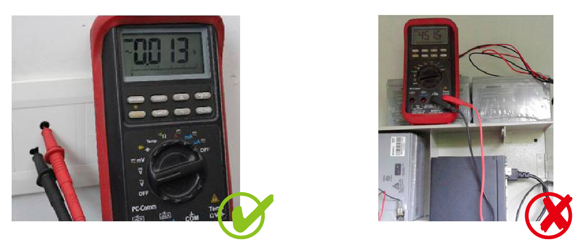
II. Choose the proper size of cabinet/enclosure with door
Improper airflow due to limited space in the network cabinet leads to switch overheating, especially for industrial applications
Benefits of a Bigger Cabinet
✓ Ample air space✓ Good airflow✓ Quicker heat dissipation✓ Better switch performance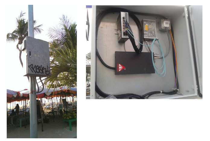
2. Correct DIN-Rail Installation and Power Inserting
I. Installation Flow Chart
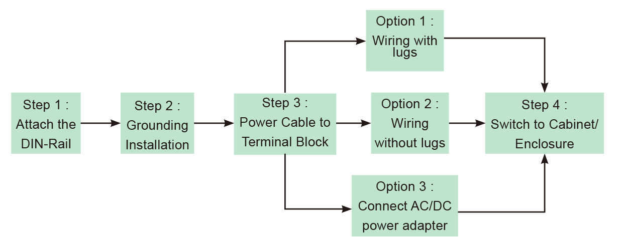 II. Step 1: Attach the DIN-Rail to the back of the cabinet/enclosure
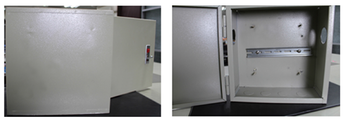 III. Step 2: Grounding Installation✓ Use a screwdriver to loosen the grounding on the switch✓ Attached the grounding lug to the M4 screw grounding receiver✓ Tighten the screws to prevent the lug from loosening✓ Place the switch on the DIN-Rail then push the front of the switch toward the mounting surface until it snaps into place with a click sound✓ Connect grounding wire to the grounding screw on cabinet/enclosure
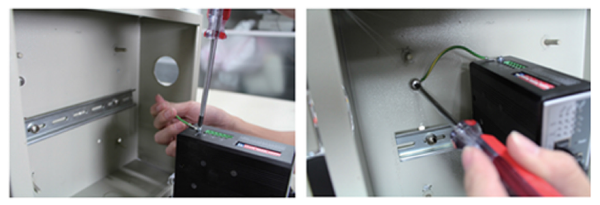 IV. Step 3: Wiring the cable and power on the switchesa. Wiring the cable✓ Use a flat-head screwdriver to loosen the wire-clamp screws✓ Insert the corresponding positive/negative into the contact receivers on the terminal block.✓ Tighten the wire-clamp screws to prevent the lugs from loosening
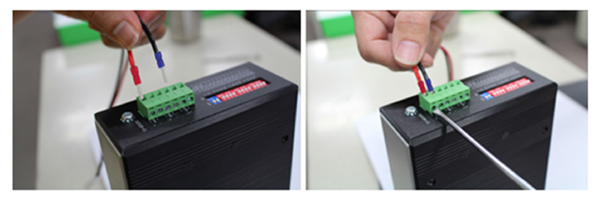 b. Power inserting and power on the switches✓ Using voltage measure to make sure the input voltage is within the range of proper power input specification.✓ Assemble the positive and negative electric wire to the terminal block correctly as in “Wiring the cable”✓ Using voltage measure to make sure the input voltage is in the operation range✓ Turn off power source✓ Plug the terminal block into the switch completely.✓ Then turn on the power source✓ After self-diagnosis, check the LED status on the switch to make sure it already successfully operated.
3. Use two available power source to prevent network interruptio
- Why does the Volktek switch lose connectivity with the Monitoring tool?
This issue is related to Monitoring tool (3rd party application)
- When should I enable the Traffic Monitoring feature on the Volktek switch?
When your switch ports are flooding with broadcast, multi-cast, and unknown uni-cast (also referred to as Destination Look-up Failure or DLF) packets and you want to block the ports.
- Can both Storm Control and Traffic Monitoring features be enabled at the same time on Volktek switch?
No. Only one feature can be enabled at a time.
- The port is not blocked after enabling the Storm Control feature on the Volktek switch. What can be the reason?
Storm Control feature only limits or restricts the packets flooding the port as configured. To block the port, enable the Traffic Monitoring feature.
- What is management VLAN? What are the benefits of network management?
A management VLAN is used to establish an IP connection to the switch from a workstation connected to a port in the VLAN and manage the switch from a remote location using protocols such as Telnet, SSH, SNMP, etc. By default, the active management VLAN is VLAN1, but you can designate any VLAN as management VLAN. Only one management VLAN can be active at a time.
Benefits
● Manage the network from a single remote location
● Better security, control and administration of network
● Improves network usage and efficiency
● Reduces administrative costs- Which ports are recommended for enabling the Loop Detection feature?
Downlink ports
- What will be the port status and LED status when the Loop Detection feature is enabled and a loop is detected?
Port status – Blocked
LED status – Off - Why does the Volktek switch lose connectivity with the Monitoring tool?
Volktek is a leading manufacturer of high-performance networking solutions which support both, today's and the Next Generation Ethernet platform.
Webmaster : Send us your comments
and questions - Click Here
-
- Contact
- 4F, 192 Liancheng Rd, Zhonghe, New Taipei 23553, Taiwan
- Tel: +886-2- 8242-1000
- Fax: +886-2-8242-3333
- Email:info@volktek.com
